Announcement

Collapse
No announcement yet.

Civic Sedan Build - JTCC Inspired

Collapse
X
 
  • Filter
  • Time
  • Show
Clear All
new posts

    Hi All,

    Here are some concept images of my front knuckle design


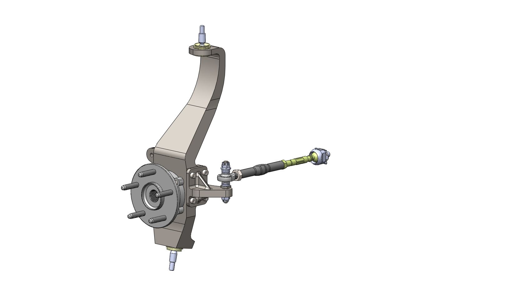
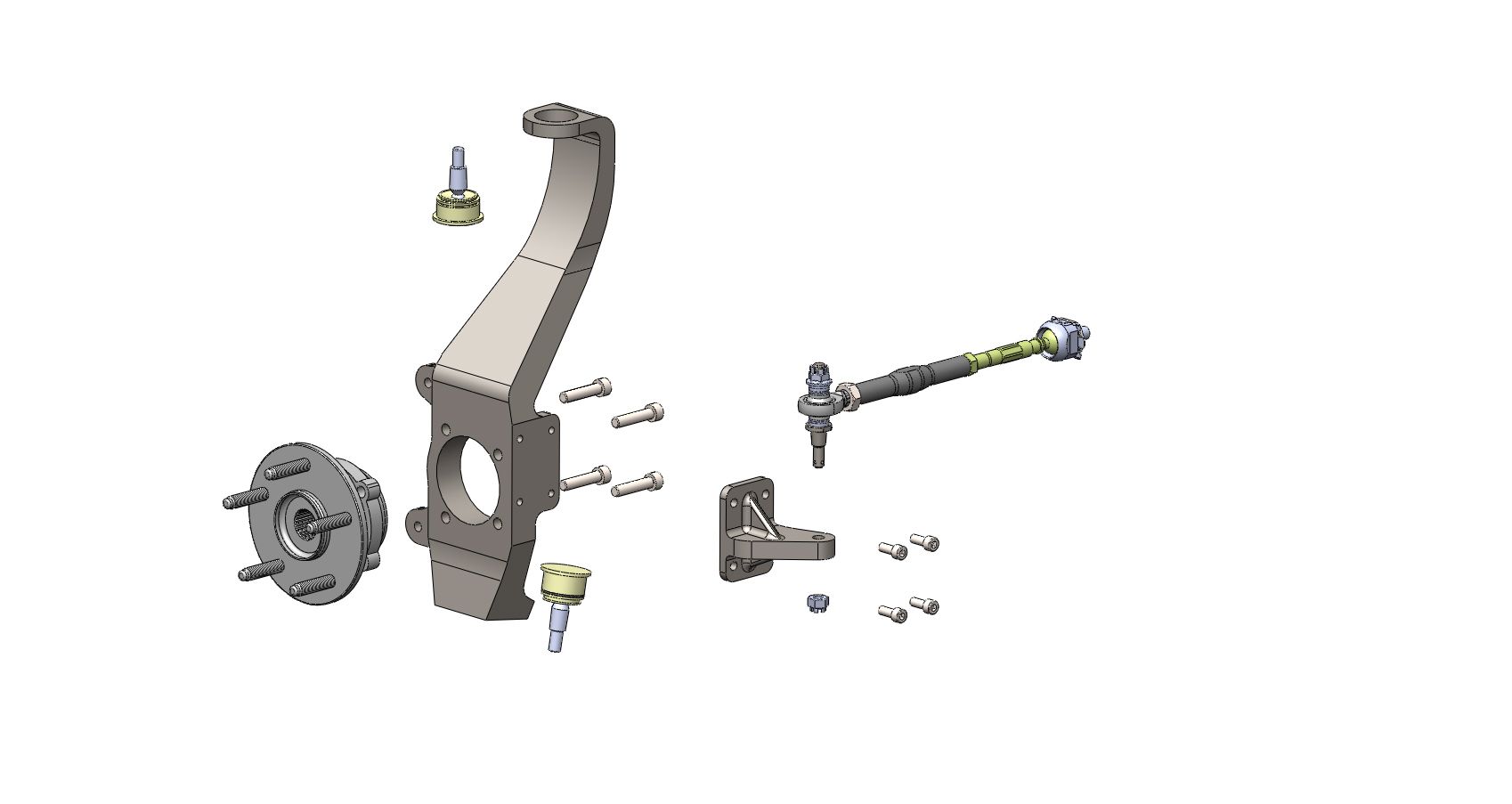
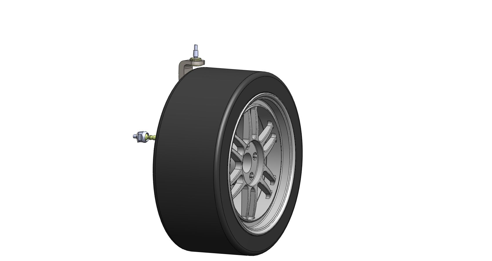
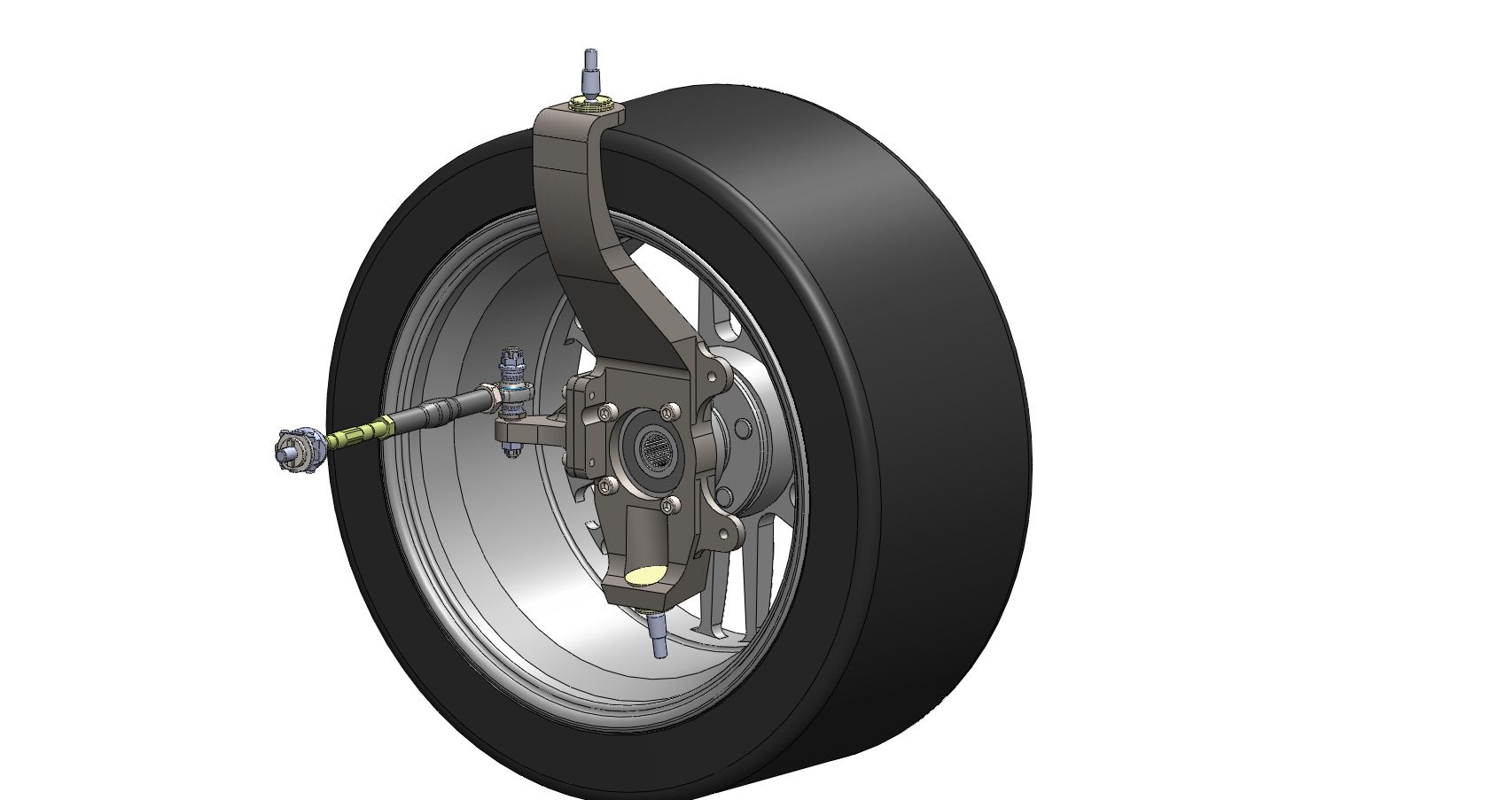
    The keen eye'd among you will notice I have two ball joints in knuckle and that the upper ball joint is upside down compared to normal

    This is an idea i'm perusing and if the geometry works out I might not have to cut and relocate the inboard end of the upper control arm (which would be nice)

    Expect lots of changes between what is shown here and the final outcome but i wanted to keep the thread updated

    I'm not even sure what method of manufacture to go with yet!

    In other news, the engine has been cleaned up

    Yesterday I received a delivery of OEM parts

    - New sump gasket

    - Head coolant passage block off plug

    - New o-rings for coolant bypass tube

    - Intake gasket

    - Gearbox side crank seal

    So i'll put those aside for when they are required.

    Next job on the shell is to drill out the spot welds and remove the brackets that mount the half size radiator and ac condenser

    Then work out how i'm going to mount the Dc2 radiator in there
    Last edited by Grant@Honed; 29-06-16, 11:02 PM.
    Honed - WEB: https://honeddevelopments.com/ FB: https://www.facebook.com/honeddevelopments

    Comment


      Nice concept. Have you decided on what materials you are going to use for the new knuckle? Something lighter then the OE part?


      Sent from my iPhone using Tapatalk

      Comment


        Nice work Grant. Concept design looks great! Did you still go with the idea to re-position the wheel hub about 40mm up from stock?
        1999 Formula Red S2000 Blog

        Comment


          I haven't selected the material yet, It would be nice if I could come up with a design that was light that stock but

          As I want to make a stiffer part, it will probably end up weight close to the same

          The concept as shown here is based on 50mm relocation of the wheel hub
          Honed - WEB: https://honeddevelopments.com/ FB: https://www.facebook.com/honeddevelopments

          Comment


            I still remember you messaging me about the rta gussets awhile back! very informative post, heaps of info in this thread that only the backyard diy'er can dream of. Very inspiring, please keep up the good updates.

            Comment


              So this Civic shell has really tidy paint work and I want to preserve that as much as possible

              I've wanted to give it a clean and put a car cover on it for the last few weeks but since I have a steep driveway out the front and the car is just a roller I have to clean it IN the garage and I wasn't quite sure the best way to do that

              I ended up just using a bucket of car wash and warm water, going around it with a sponge, covering it in suds and then rinsing the sponge out and just wiping it down again with water

              It was deeply satisfying to see the shine come back to the paint, I've got a cheap car cover for it now and I just roll it back and forth depending on what I'm working on


              The dash is just sitting there for now, but you can see I've stripped all the sound deadening out


              I'm not sure what to do with the rear of the car

              I would like to create a firewall between the boot and the cabin so that I can mount my power steering in the boot but i'm not exactly sure how to go about sealing it off yet

              I know I want to have a half cage at the very least and so any paneling will have to dodge around the rearward bars of the cage...


              The engine bay has been scrubbed down, I removed the original fuel filter today as in the stock location it would clash with my new intake set up

              I'm thinking i'll run an aftermarket e85 compatible one and mount it lower down on the firewall


              Speaking of the intake...

              I've finished all the design work, i've made drawings for all the parts I need machined and will be getting those out for quote on Monday


              The throttle body flange will be welded to the plenum


              And I will be welding a block with 1/8 NPT female threads in it underneath for the vacuum ports


              I've cleaned up the TB


              I still have to source a gasket and wiring diagram for it
              Last edited by Grant@Honed; 10-07-16, 05:32 PM.
              Honed - WEB: https://honeddevelopments.com/ FB: https://www.facebook.com/honeddevelopments

              Comment


                This afternoon I also had a look at mounting the ethrottle pedal

                Thankfully it looks like it will be really straight forward

                I've cut back the bracket where the accelerator pedal mounts and looking at it, I should be able to mount the new pedal assembly with a laser cut plate welded to the brake pedal mount and a secondary clamping plate to hold it at the bottom


                As long as I can get the pedal in the approximate location, I can fine tune it by tweaking the pedal itself

                I notched the firewall so that the master cylinder can be mounted with my booster delete plate


                Revision A of my booster delete plate was a bit thin resulting in the cap of the master cylinder reservoir rubbing on fire wall. I've modified the design to improve the position of the MC and I'll have another plate made


                And finally, I bought some water line and made up a section from the head to the thermostat housing


                Thanks for reading!
                Last edited by Grant@Honed; 10-07-16, 05:33 PM.
                Honed - WEB: https://honeddevelopments.com/ FB: https://www.facebook.com/honeddevelopments

                Comment


                  Hi All,

                  Today I got a few hours in the garage to work on the car

                  I spent some more time thinking about the front suspension set up

                  Since the update where I posted a CAD image of a custom knuckle I've changed my mind on the direction that I want to go (at least initially)

                  I'm now leaning heavily toward modifying the standard knuckles to achieve the geometry that I want

                  The concept I'm working to now is to drill out the upper ball joint and somehow (i have a vague plan) mount a spherical bearing under the bottom face of the upper ball joint mount part of the knuckle ( between the knuckle and the tyre)

                  I got the idea from this images on PCI's website

                  http://www.pci-racing.com/gallery/


                  By my estimation there is just enough room to do this, I will need to make a custom upper control arm to make this work

                  Then i'm going to get an oem lower ball joint and turn the shoulder off it and mount it in a custom extension to offset it downward 50mm


                  I will also have to relocated the tie rod downward 50mm this means it will end up below the steering arm but since I already have a 1/2" rod end for my out tie rod this will be easy enough to do

                  I have started planning how i'm going to tub the front arches


                  I got my friend Tom to put a couple of stitches on my accelerator pedal mount.

                  As soon as my master cylinder mount arrives I will be able to mock up the pedals and find out if the current positioning is close or not


                  I then turned my attention to mounting the radiator, as I mentioned previously, I purchased ASR's lower radiator mounts

                  I decided to use oem honda upper radiator mount bushes in the billet mounts so that I could get the radiator sitting just that little bit lower


                  I have seen one other person mount the ASR brackets and they had them sitting on top of the valance flange, I found this would have resulted in the radiator sitting too high so I've mounted them on the bottom face


                  Can anyone tell me if the radiator position fore-aft looks alright? I feel like it is*sitting further into the engine bay than standard. Could this be an issue for header clearance?

                  I went to the pick-a-part this morning and while I was there I picked up two EK upper radiator mount brackets thinking that I might be able to use them to constrain the top of the radiator

                  Well as it turns out they don't really line up with any holes or even the flat part of the panel between the headlights but they do appear to be roughly the right height

                  So I'm going to make up a panel that performs two functions

                  1) Provides mounting points for the EK radiator brackets

                  2) Seals the gap between the panel and the radiator


                  I'll get the panel made from aluminium and ask for m6 nutserts in the locations where the EK upper radiator brackets need to be bolted down


                  This week I hope to receive some more bits for the engine and engine oil cooler set up

                  Thanks for reading!
                  Last edited by Grant@Honed; 06-08-16, 06:59 PM.
                  Honed - WEB: https://honeddevelopments.com/ FB: https://www.facebook.com/honeddevelopments

                  Comment


                    Just read your thread from the beginning. What a read! Given me some good ideas for my DC2 and has put into perspective the amount of work that goes in

                    Comment


                      I got a new camera tonight and I thought i'd try it out by taking some photos in the garage.


                      Also the machined intake parts arrived last week, I have confirmed that the flange fits the head

                      I tried to mock up the intake completely with fuel rail and injectors but the oem fuel pressure reg hits the plenum flange

                      I think i'm just going to get a -6 fitting welded to the fuel rail and mount an aftermarket regulator to the firewall


                      Bear with me while I work out how to use this camera and get a better lighting situation sorted out
                      Last edited by Grant@Honed; 17-08-16, 10:58 PM.
                      Honed - WEB: https://honeddevelopments.com/ FB: https://www.facebook.com/honeddevelopments

                      Comment


                        Originally posted by Alex_Walker View Post
                        Just read your thread from the beginning. What a read! Given me some good ideas for my DC2 and has put into perspective the amount of work that goes in
                        Thanks Alex!
                        Honed - WEB: https://honeddevelopments.com/ FB: https://www.facebook.com/honeddevelopments

                        Comment


                          A few weeks back I made the image below my desktop background, I did so partly for aesthetic inspiration and partly as a constant reminder to myself to keep chipping away at all the tasks that come with a project like this

                          One night while staring blankly at my screen I noticed that the car only has one windscreen wiper!

                          I was vaguely aware that of some BTCC and Supertouring cars only had the one wiper but until that moment didn't realise that was something done to the JTCC civics


                          And so I started thinking about how they might have achieved this

                          My first thought was that perhaps they used a rear windscreen wiper assembly out of another vehicle, a CRV or Odyssey, something along those lines with a large rear window

                          I was discussing this one night with Tom at his workshop when we realised that his CRX still has the scuttle panel missing and that we would be able to have a good look at the wiper mechanism on his car

                          After familiarizing ourselfves with how the factory front wiper assembly works

                          We reasoned that it might be possible to remove the driver side wiper and just index the passenger side wiper on it's spline

                          So that was the plan when I got into the garage this afternoon

                          What I soon found out was that the original front wipers from the EG were going to be way too long to use in this way

                          So with measuring tape in hand I made a quick trip to the local pick-a-part in search of a suitable wiper

                          I found one on the back of a station wagon that was about the right length (and bent the "other way" and took it home

                          If you compare the length of the wiper on my car below to the one in the top image it's not too far off!


                          I connected a spare battery directly to the wiper motor to test the range of motion of the wiper


                          Video of the wiper motion
                          https://www.youtube.com/watch?v=80HS...ature=youtu.be

                          When I refitted the scuttle panel it restricted the range of motion toward the drivers side so i'll give that a trim next time


                          With the standard linkage untouched, the wiper makes it just over halfway across the screen


                          It's hard to know how much wiper coverage I'm really going to need for this car (not much I reckon)

                          But looking at this photo it looks like the JTCC car's achieved a bit more angle


                          I'll probably leave it as is for now and look into modifying the linkage in the future
                          Last edited by Grant@Honed; 21-08-16, 09:21 PM.
                          Honed - WEB: https://honeddevelopments.com/ FB: https://www.facebook.com/honeddevelopments

                          Comment


                            very cool idea!

                            Comment


                              Haha! Boy does this bring me back 20+ years!

                              I had a VTi EG back in '94-'96 and what we used to do was just shift the wiper arms. From memory, I just interchanged the arm and wiper blade, sat it at about 45deg and ran off the passenger wiper motor.

                              Edit: And the rego number just popped into my head! It was white, with sunroof, rego FLT203! How's that for a freaky recall?

                              Comment


                                I was excited to get into the garage this morning because yesterday I received a 3d printed version of my latest brake booster delete plate design and I was egar to see how it looked


                                I have changed the mounting pattern of my booster delete plate to a horizontal two bolt pattern so that I can use Honda EK Civic master cylinders. The previous design used an EF master cylinder and in that mounting style there were limited cylinder sizes available

                                To the other side of the firewall now

                                As I have already shown, I have cut the original accelerator pedal off the brake pedal bracket and mounted a Holden Commodore electronic throttle pedal in it's place


                                I allowed some for some adjustment of the commodore pedal by slotting the mounting holes (up and down) I was also thinking that if it was drastically out the I could always just bend the pedal

                                Today I mounted it in place and sat in the drivers seat to try it out

                                By a complete fluke it is in the perfect position, from what I can tell without driving it at least

                                Feels just nice beside the brake pedal

                                The pedal stop on the back of the pedal even contacts the firewall just before the pedal runs out of travel which is ideal

                                Stoked with that result


                                I have modified an old knuckle similarly to how I intend to modify my actual knuckles (without the box section obviously hah)

                                The idea being that I will be able to check the driveshaft lengths, clearances and work out a design for the upper control arm using this beater knuckle


                                One thing that this exercise has uncovered is that there is not a whole lot of room between the spherical bearing which is to be my new upper ball joint and the knuckle

                                This is a 1/2" bolt and 1/2" spherical so after looking at this I have decided to downsize this to 3/8" which beacuse the bearing race is smaller gains me another 2.5mm in that gap


                                This is an exploded view showing the modification I intend to do to the knuckle

                                Various bushes and spacers


                                Before I commit and send my drawings out for the knuckle modification parts I thought I better measure the suspension geometry one last time just to be sure what I intend to is going to work

                                I pulled the shock out of the LHS and then set the car up as if the ride height was 300mm wheel centre to guard


                                Took a bunch of measurements


                                Put those measurements into CAD, I've got alot of the components measured and modeled already so I only really need to take a few key measurements and then I can generate a 2d traverse corner model

                                Then I superimposed the geometry of the modified knuckle and checked that It was all going to work out as intended


                                The biggest thing to come out of this is that I can't quite get the lower ball joint as low as I'd like because it:

                                Will hit the inside of the brake rotor
                                Hit the inside of the rim
                                But were only talking like 10mm short of ideal so it's not a major.

                                I guess that's why the later generation touring cars eventually when to 18's and 19's!
                                Honed - WEB: https://honeddevelopments.com/ FB: https://www.facebook.com/honeddevelopments

                                Comment

                                Working...
                                X