DIY: B series valve clearance adjustment
What follows is a guide to adjusting the valve clearance on a B16A. It seems to be a job that a dealer will charge an arm and a leg for and do a shoddy job of so it is worth trying yourself. The procedure is nearly identical for any other B series VTEC motor and also similar for the K series except they spin the other way.
ClubITR and myself take no responsibility for any mischeif or misfortune that may befall you if you attempt this diy, please only proceed if you have the correct tools and adequate mechanical knowledge. If you are unsure of anything then just ask. If you think there are any errors or omissions then please post up and let me know.
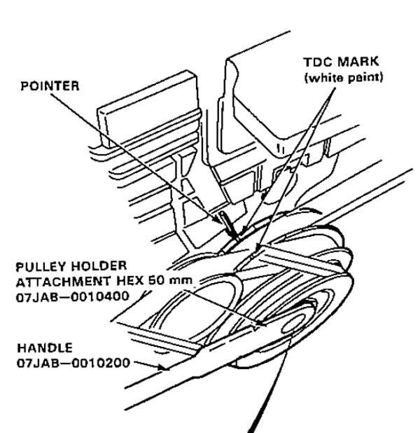
Here are the relevant pages of the EE8 CRX VTEC supplement, be sure that you follow the manual for your own car so the valve clearances are correct:


Here are the tools you will need:
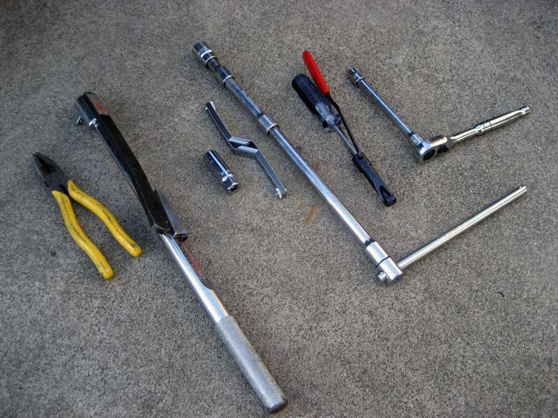
10mm socket
3/8" drive ratchet
Various extensions
19mm socket
1/2" drive slide bar
Angled feeler gauge
Spark plug socket
Torque wrench (I used this one for the wheel nuts, you will need a smaller one for the valve locknuts)
Pliers
Valve adjustment tool (I got mine from eBay)
Jack (not pictured)
Jack stands (not pictured)
Hondabond (not pictured)
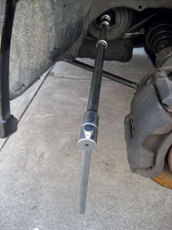
1. Loosen the wheel nuts on the front passenger site wheel. Raise the front of the vehicle using a floor jack and support with safety stands, pictured in Figure 1 (note that you might not be lucky enough to have a manky old CR-X). Remove the front passenger side wheel as depicted in Figure 2 and any splash shields that might be in the way of the crank pulley, you should be faced with something like what is pictured in Figure 3.
Figure 1: The car safely on stands
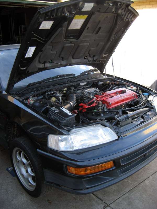
Figure 2: The wheel
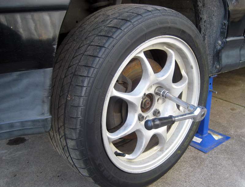
Figure 3: The crank pulley

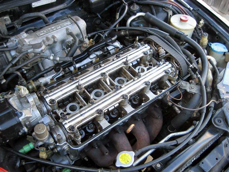
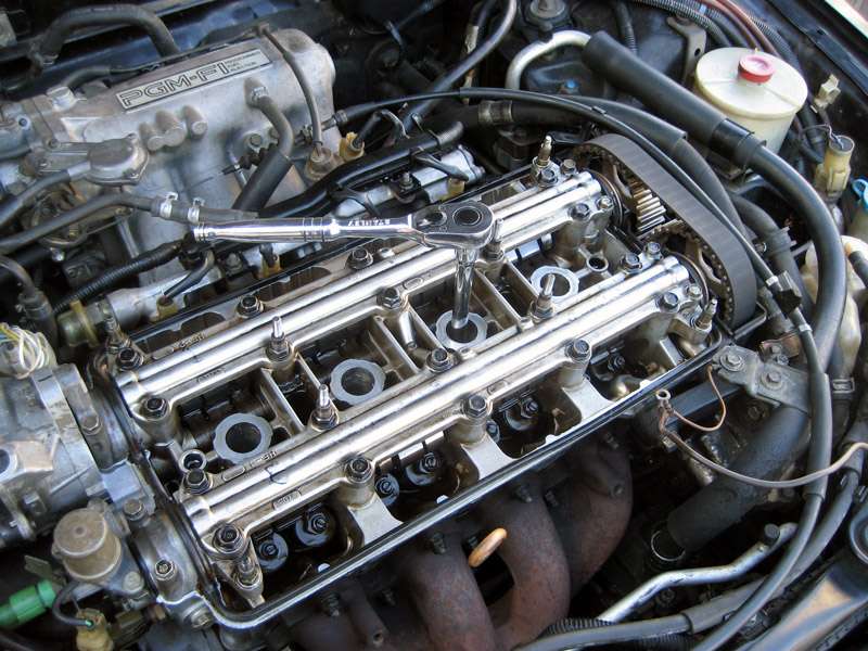
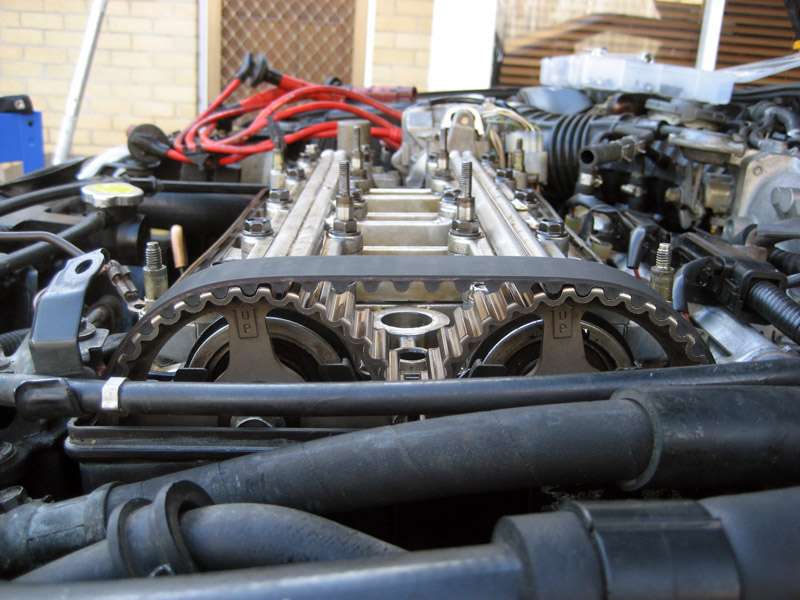
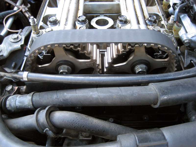
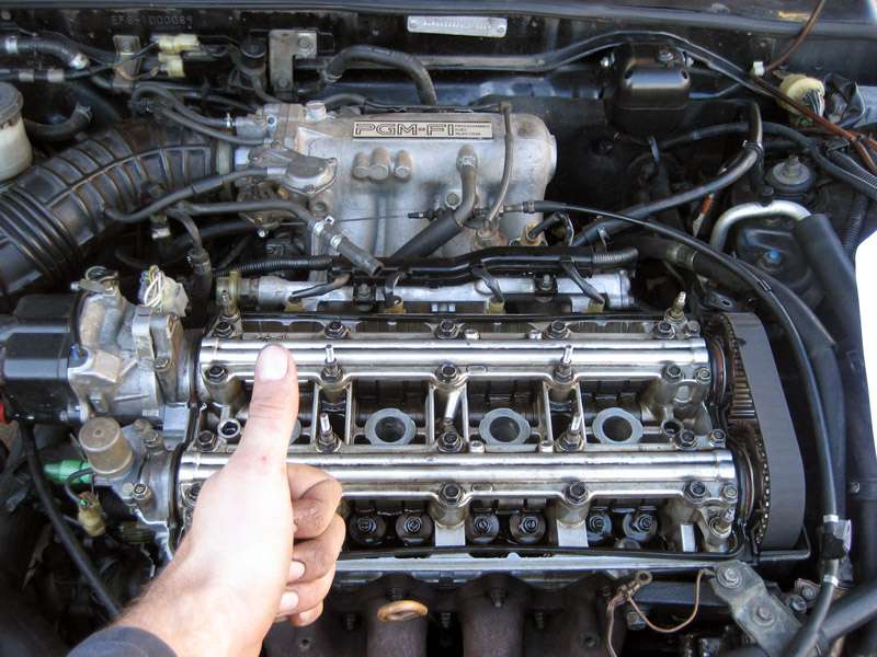
2. Remove the spark plug cover by removing the 4 10mm bolts, pictured in Figure 4. Remove the valve cover by removing the 8 10mm nuts along with any random bolts holding brackets around the periphery of the valve cover as pictured in Figure 5. Remove the valve cover breather that goes to the intake by firstly moving the spring clamp with pliers and then gently pulling the tube off, as in Figure 6. Lift off the valve cover, you should be looking at something that looks like Figure 7. Note that in my case the old manky valve cover gasket stuck to the head, you should remove this too but I left it there as I didn't care if I messed it up because I was replacing it.
Figure 4: Plug cover removal
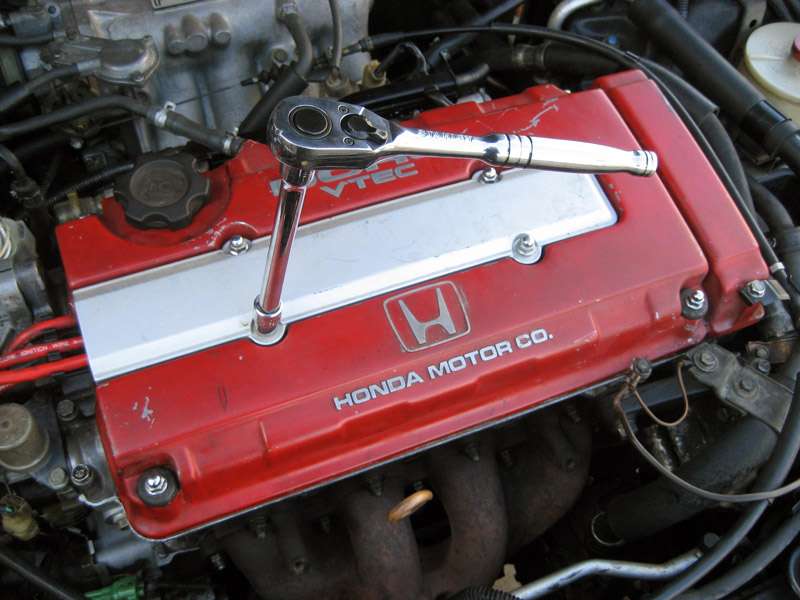
Figure 5: Valve cover removal
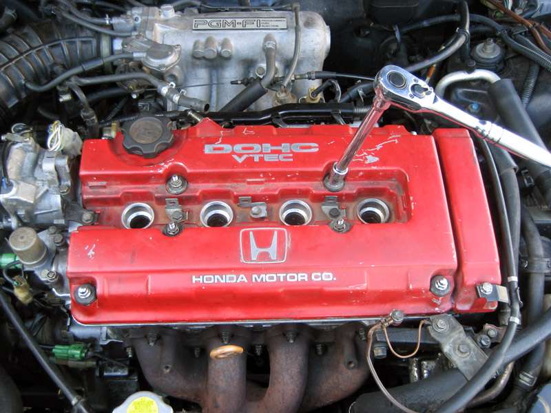
Figure 6: Breather removal
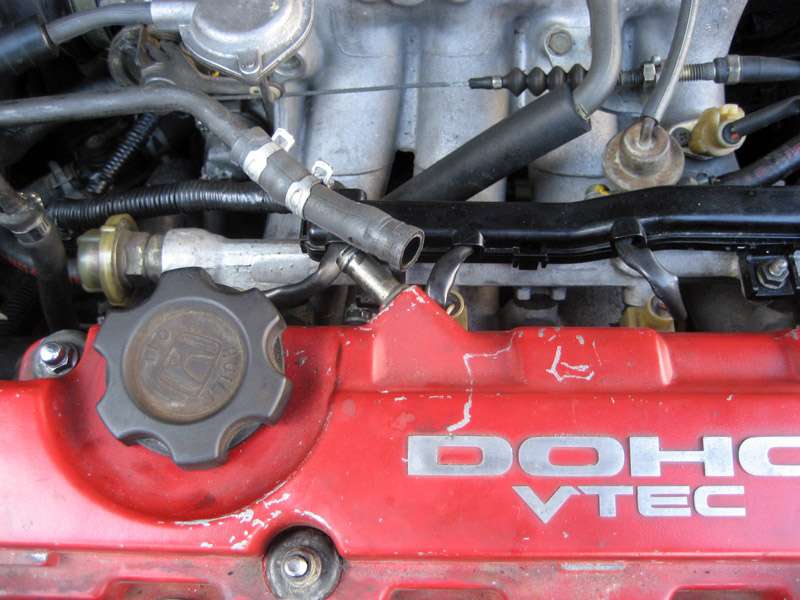
Figure 7: The valvetrain
What follows is a guide to adjusting the valve clearance on a B16A. It seems to be a job that a dealer will charge an arm and a leg for and do a shoddy job of so it is worth trying yourself. The procedure is nearly identical for any other B series VTEC motor and also similar for the K series except they spin the other way.
ClubITR and myself take no responsibility for any mischeif or misfortune that may befall you if you attempt this diy, please only proceed if you have the correct tools and adequate mechanical knowledge. If you are unsure of anything then just ask. If you think there are any errors or omissions then please post up and let me know.
Here are the relevant pages of the EE8 CRX VTEC supplement, be sure that you follow the manual for your own car so the valve clearances are correct:
Here are the tools you will need:
10mm socket
3/8" drive ratchet
Various extensions
19mm socket
1/2" drive slide bar
Angled feeler gauge
Spark plug socket
Torque wrench (I used this one for the wheel nuts, you will need a smaller one for the valve locknuts)
Pliers
Valve adjustment tool (I got mine from eBay)
Jack (not pictured)
Jack stands (not pictured)
Hondabond (not pictured)
1. Loosen the wheel nuts on the front passenger site wheel. Raise the front of the vehicle using a floor jack and support with safety stands, pictured in Figure 1 (note that you might not be lucky enough to have a manky old CR-X). Remove the front passenger side wheel as depicted in Figure 2 and any splash shields that might be in the way of the crank pulley, you should be faced with something like what is pictured in Figure 3.
Figure 1: The car safely on stands
Figure 2: The wheel
Figure 3: The crank pulley
2. Remove the spark plug cover by removing the 4 10mm bolts, pictured in Figure 4. Remove the valve cover by removing the 8 10mm nuts along with any random bolts holding brackets around the periphery of the valve cover as pictured in Figure 5. Remove the valve cover breather that goes to the intake by firstly moving the spring clamp with pliers and then gently pulling the tube off, as in Figure 6. Lift off the valve cover, you should be looking at something that looks like Figure 7. Note that in my case the old manky valve cover gasket stuck to the head, you should remove this too but I left it there as I didn't care if I messed it up because I was replacing it.
Figure 4: Plug cover removal
Figure 5: Valve cover removal
Figure 6: Breather removal
Figure 7: The valvetrain

Comment